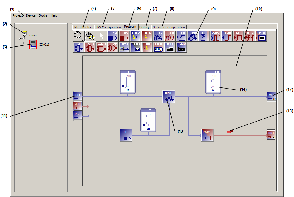

| (1) – Top Menu bar. - The Project function allows you to start a new project, open an existing one, close a project, save the current project and exit MBus_ioFlash. - The Device function allows you to add or delete devices to your open project. - The Blocks function allows a cut/copy/paste/delete of a selection of function blocks (single block or multiple selection). - The Help function provides help on MBus_ioFlash. (2) – This icon displays the Project type. The Pro version of MBus_ioFlash introduces support for multiple communication networks in the same project, and these can be either local COM ports or remote Gateways. (3) – Devices area. This is the list of all the devices in your project. Five tabs are available for each device of the project: (4) – The identification tab. Allows you to identify a specific device using a name and an address (5) – The Hardware configuration tab. All adjustable hardware parameters (i.e, I/Os, displays, etc) are configurable in this tab. (6) – The Programming tab. This is where control loops are created for each of the devices in the project. Also, the workspace vie is controlled via a zoom button and you can toggle between the programming and the simulation mode via push buttons. (7) - The History tab. Allows the graphical live view of selected parameters. (PRO version only) (8) - The Sequence of operation tab. Allows entering textual information and instructions associated with the device and its programming. This information will be saved along the specific device inside the project file. (9) – Function blocks and workspace control buttons. (10) – Workspace. Click on function blocks and drag them to the workspace and link them with I/Os and other function blocks to create custom control algorithms (11) – Analog (blue) and digital (red) inputs. (12) - Analog (blue) and digital (red) outputs. (13) – Function block linked with I/Os and other blocks. (14) – Interactive analog monitor. In simulation mode, it shows the block's current value as a bar graph and also in numerical form at the bottom. (15) - Interactive digital monitor. In simulation mode, it shows the state of a digital signal. |