Any device that can be programmed with MBus_ioFlash software automatically supports the Modbus protocol and can provide and accept data from a Modbus master controller. Any one of the defined function blocks can be assigned a Modbus register address, this address will be used by a Modbus master controller to access the block's value.
NOTE: Modbus addresses 1 to 19 are reserved for internal use. We recommend starting at register 100 or higher to leave room in case more registers need to be reserved in the future.
To make a block's value accessible via Modbus simply enter a register number as shown below.
![]()

Modbus broadcasts are also supported. Modbus broadcasts are simply write register commands with the device address set to ‘0’. In this case the device will act on the write command but will not send an acknowledgement response message. For additional security, only blocks with the “Accept
Broadcasts” option selected will accept broadcasts.The modbus registers use a 16 bit signed integer data format by default, which can be read using Modbus function code 3 (read Holding registers) and written using Modbus function code 6 (Write Single Register). Some systems however support additional data formats. In addition to the standard 16 bit signed integer format the devices also support a IEEE 754 32 bit floating point format. You can select this format by clicking the "Float32" option in the Modbus parameters.
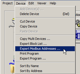
At any time the user can create a text file describing all Modbus addresses currently defined for a device. Select the "Export Modbus Address ..." item from the "Device" menu as shown below.

This will create a text file containing all the defined Modbus register addresses for the selected device, a sample is shown below:
| Modbus Addresses for Device: IO(01) Address, Blk Name, Format 00101, DO1, (0)Off/(1)On 00102, DO2, (0)Off/(1)On 00103, DO3, (0)Off/(1)On 00104, DO4, (0)Off/(1)On 00105, PWM1, (0)Off/(1)On 00201, Tint, o C X10 00202, AI1, o C X10 00203, PID1, % X10 00204, SP, o C 00205, OUT, |