Device programming is done via the Program Tab while in edit mode. To create an embedded control algorithm for a device you must select and deposited a series of interconnected function blocks onto the programming page. Click on the desired function block menu bar and then click on the program page in the position where you want it to be place. Once a function block is on the programming page you can double-click it to expose it's definition dialog box.
Program tab display notes:

Each function block definition dialog box contains parameters that are specific to the type of function block selected. The following describes parameters that are common to all function block types.
Note: The Sequence of operation tab allows entering textual information and instructions associated with the device and its programming. This information will be saved along the specific device inside the project file.
| Parameter |
Description |
|
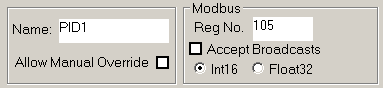
All function blocks allow you to define a name for the block. A name can be any combination of alphanumeric characters up to a maximum of 8 that is unique from other blocks on the device's program page.
If you select the "Allow Manual Override" option you will be able to put a block to manual while in run mode on the MBus_ioFlash programming page. When a block is in manual mode you can freely set the block's value and it will not be overwritten by the MBus_ioFlash algorithm. To put a block into manual mode hover the bottom righthand corner of the block and click to toggle it to manual mode or to put it back to auto mode. |

|
The Description field allows entering textual information and instructions associated with the programming block. Note: if the Description field is used and has specific content, hovering the mouse over, or clicking, the upper-left corner of the block will generate a quick view of the description. Allows a quick view without the necessity of opening the Block Editor. |
 |
Most analog blocks definition dialog boxes will contain these three parameters. Together they define the analog value's range and how it should be displayed. The scale will be used on the iStat device display to limit user's input to remain within the defined range. |
|
|
Many of the function block parameters have the (Dyn) option. This indicates that the parameter can optionally be dynamic. Selecting the DYN button will allow you to assign an other block to provide the value of the parameter instead of entering it statically. |
|
|
All digital blocks offer a Normal/Invert output option (toggle button), allowing the inversion of the logical digital output of the block. |
|
|
Mixed inputs toggle button. By default, analog or digital inputs will only allow you to select inputs of the correct type, analog or digital. The toggle button will be blue for analog blocks or red for digitals. If the toggle button is pushed, (half blue and half red icon) the restriction is relaxed allowing mixed connections, (analog outputs can be connected to a digital input or a digital output can be connected to an analog input). If an analog is connected to a digital input any value other that zero is considered "true". If a digital is connected to an analog input then a "true" is interpreted as the value 1.0 while a "false" is interpreted as the value 0.0. |


 /
/