Device Programming |
|
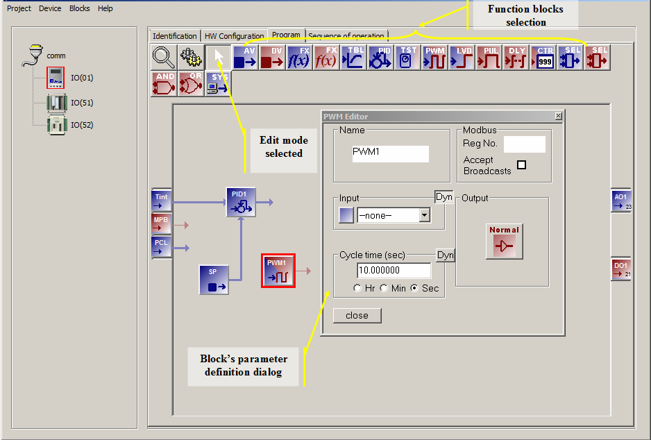
The Program tab allows access to the device's embedded program, from this tab you can create the actual control algorithm that will be downloaded into the device. Initially the programming tab is set to the edit mode which is indicated by the selection of the arrow cursor icon at the top.
To create a program you will select function blocks from the top row of icons; drop them in the workspace; and then double-click them to access each block's parameter definition dialog. Connections among the blocks are done by setting the input parameter selections on each block's parameter definition dialog. Note that the I/O pins previously defined on the Hardware Configuration tab appear as blocks on the left or right hand side of the workspace, left hand for inputs, right hand side for outputs.
For the purpose of this tutorial we will create a simple temperature controller.
| Step 1 | Insert a PID function block. This block implements a standard PID control algorithm. | 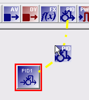 |
| Step 2 | Insert an AV function block. This type of block simply holds an user settable analog value. It will be the temperature set-point. Its name can be changed to "SP" by double-clicking the block and modifying the "Name" field. | 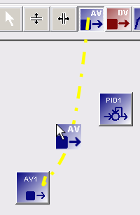 |
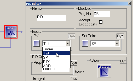
| Step 3 | Now we will do the input connections to the PID1 function
block. Double-click the PID1 function block to invoke its parameter
definition dialog and set the "Input" parameter to
"Tint" the temperature input block. Similarly, set the PID1's "Set Point" parameter to "SP", the block we created in the previous step. |
 |
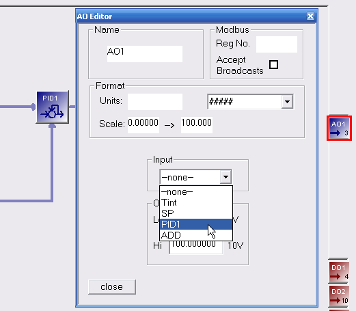
| Step 4 | We will use the analog output block AO1 to drive the heater element. We assume that we have a power amplifier compatible with a 0 to 5V signal. To connect it to the PID control output, double-click the AO1 block to invoke its parameter definition dialog and set the "Input" parameter to "PID1". |
 |
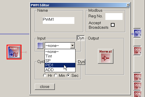
| Step 5 | Alternatively, if we do not have a linear power amplifier to drive the heater element we can drive it via a PWM (Pulse Width Modulation) block. To add it simply select and drop a PWM type function block and connect it's "Input" parameter to "PID1". Then connect its output to one of the digital output blocks, DO1, for example. |
 |
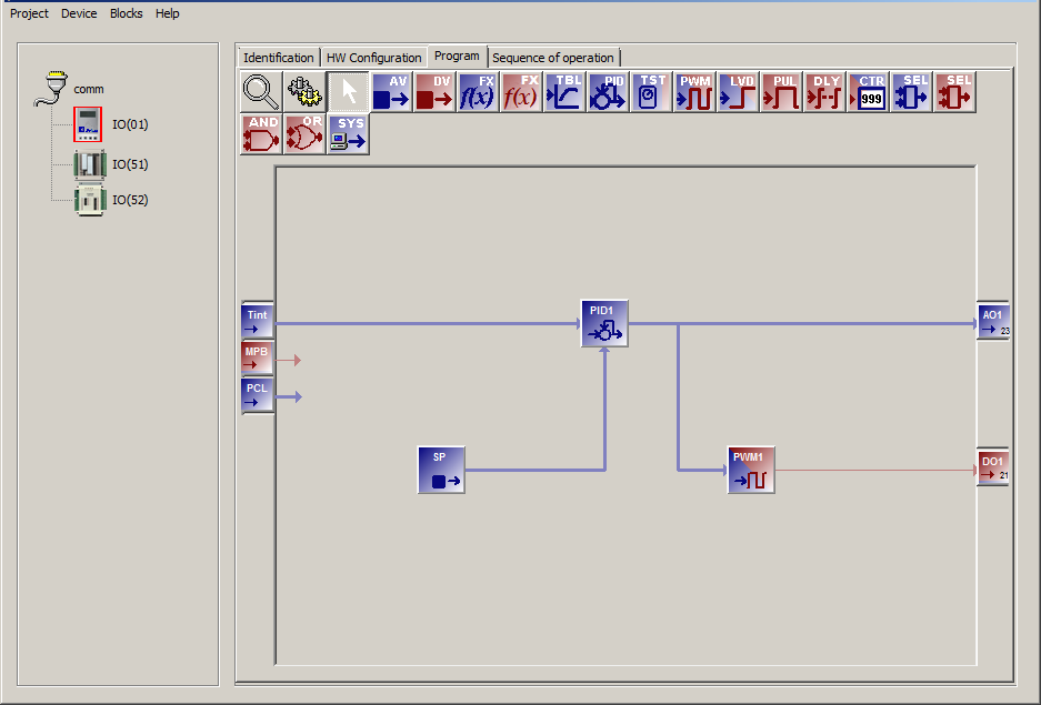
Congratulations you have successfully created a temperature control program for your device. This program can now be downloaded and run on the target embedded device. Your final program should look like the one shown below.